
A wire harness can be built with the highest quality Mil-Spec wire, the finest gold-plated terminals, and impeccable crimps – but if the next technician doesn’t know what it connects to, it is virtually useless. In the complex world of electrical engineering, a wire harness is only as good as the documentation that accompanies it.
Whether you are building a one-off prototype or preparing a harness for mass production, properly documenting and labeling your assemblies is crucial for successful installation, future troubleshooting, and safety. Here is a comprehensive guide on how to do it right.
1. The Foundation: Accurate Schematics
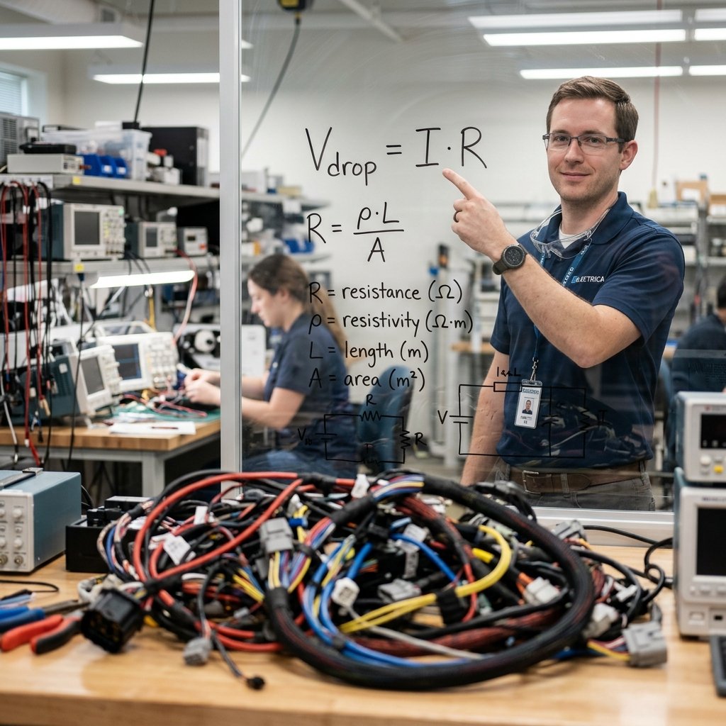
Every wire harness project must begin with a detailed electrical schematic. Hand-drawn sketches are no longer acceptable in professional manufacturing. Software tools like AutoCAD Electrical, SolidWorks Electrical, or specialized harness design software should be used.
An excellent schematic must include:
- Wire Specifications: Clearly denote the AWG (gauge), color, and insulation type for every single wire.
- Pinouts: Detailed diagrams of every connector showing exactly which wire goes into which pin cavity (e.g., “Pin 1: +12V Red, Pin 2: Ground Black”).
- Splice Locations: If wires are spliced together inside the harness, the exact physical location of that splice must be noted.
2. The Physical Nail Board (Formboard) Diagram
While the schematic shows the electrical logic, the nail board diagram shows the physical layout. This is a 1:1 scale drawing printed out and glued to a wooden board. Assemblers hammer nails into the board to trace the routing paths.
The nail board documentation ensures that every “branch” (breakout) of the harness exits the main trunk at the exact millimeter required to reach its intended sensor or component. It should also specify where zip-ties, tape wraps, and protective loom begin and end.
3. Physical Labeling Methods
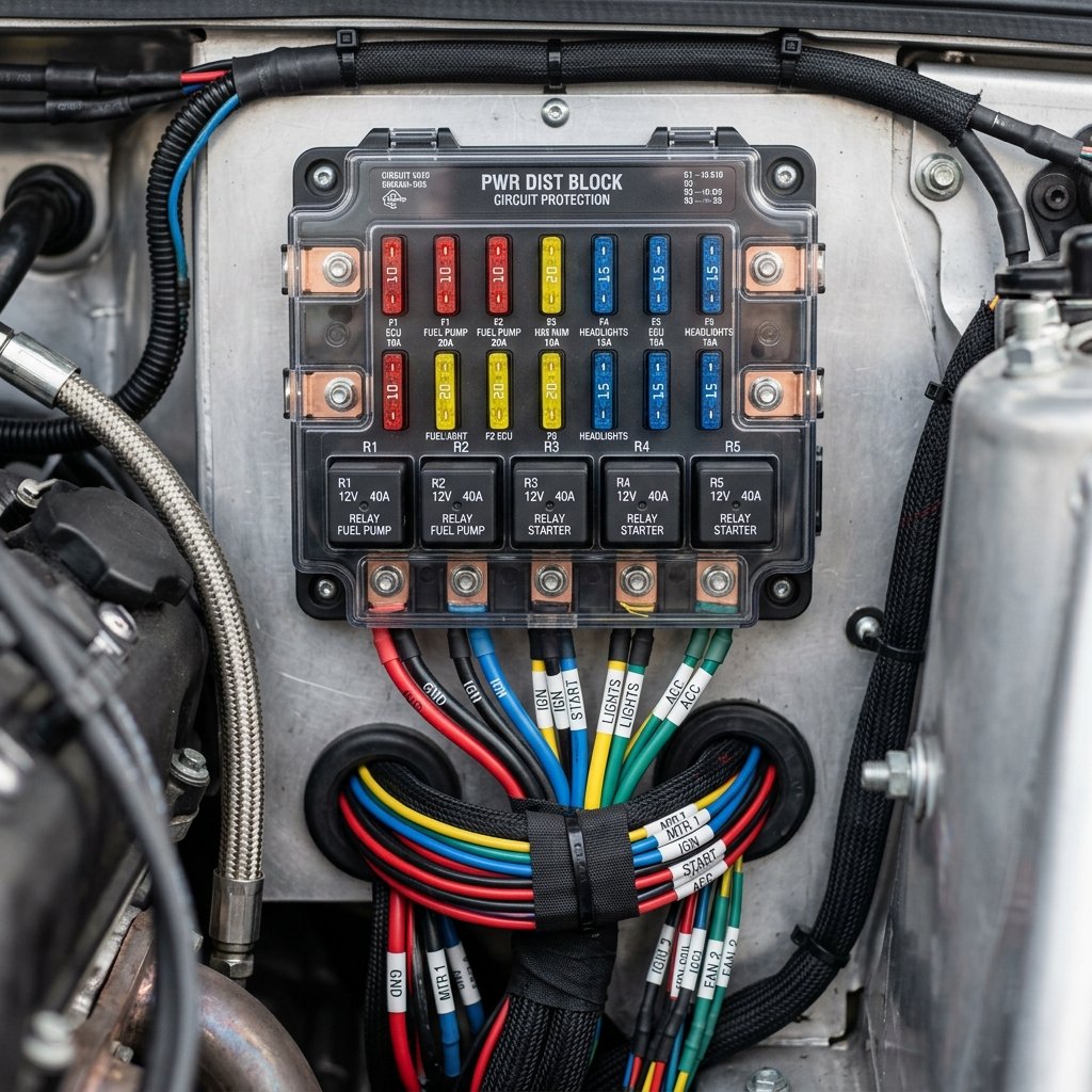
Documentation on paper is vital, but physical labels on the harness itself are what save the day in the field. When a mechanic is staring at a massive bundle of wires under a dashboard, they need immediate visual cues.
Best Practices for Labeling:
- Wrap-Around Cable Markers: These are self-laminating vinyl labels. You print the text on a white section, wrap it around the wire, and the clear tail wraps over the text to protect it from oil and dirt.
- Printable Heat Shrink Tubing: The ultimate OEM standard. A specialized thermal transfer printer prints directly onto flattened heat shrink tubing. The tube is slipped over the wire and shrunk down for a permanent, highly professional, non-removable label.
- Label Every Breakout: At a minimum, there should be a label near every connector identifying its target component (e.g., “O2 SENSOR BANK 1” or “MAIN ECU J1”).
4. Standardizing Your Naming Conventions
Consistency is key. Do not label one connector “Fuel Pump” and another “FP-1”. Develop a standardized naming convention and stick to it across your schematics, Bill of Materials (BOM), and physical labels.
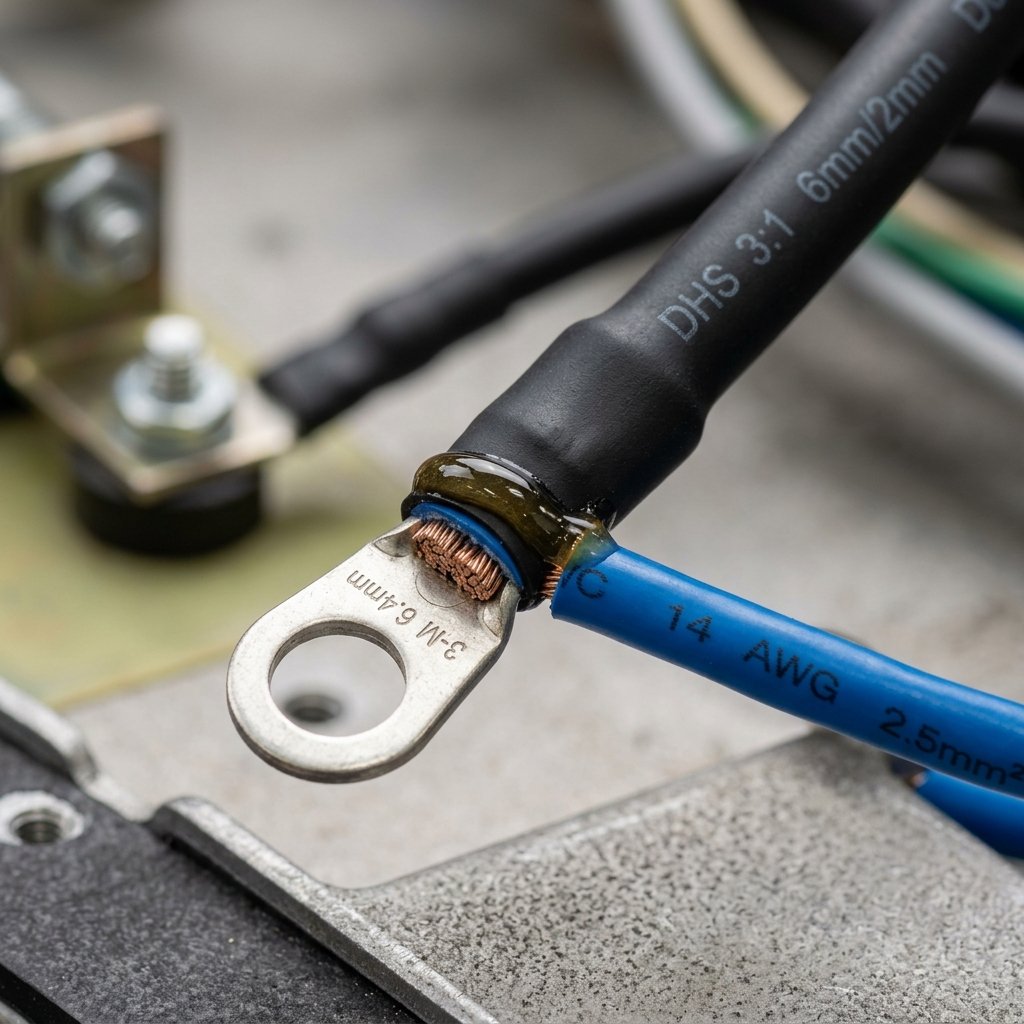
A common method is assigning alphanumeric codes. Connectors might be labeled C101, C102, etc. Splices might be S201, S202. This allows for a clean, concise physical label on the harness that directly references a highly detailed row in the master wiring manual.
Quick Step Guide
-
The Foundation: Accurate Schematics
Every wire harness project must begin with a detailed electrical schematic. Hand-drawn sketches are no longer acceptable in professional manufacturing. Software tools like AutoCAD Electrical, SolidWorks Electrical, or specialized harness design software should be used.
-
The Physical Nail Board (Formboard) Diagram
While the schematic shows the electrical logic, the nail board diagram shows the physical layout. This is a 1:1 scale drawing printed out and glued to a wooden board. Assemblers hammer nails into the board to trace the routing paths.
-
Physical Labeling Methods
Documentation on paper is vital, but physical labels on the harness itself are what save the day in the field. When a mechanic is staring at a massive bundle of wires under a dashboard, they need immediate visual cues.
-
Standardizing Your Naming Conventions
Consistency is key. Do not label one connector “Fuel Pump” and another “FP-1”. Develop a standardized naming convention and stick to it across your schematics, Bill of Materials (BOM), and physical labels. A common method is assigning alphanumeric codes. Connectors might be labeled C101, C102, etc.
For related reading, see our article on a beginner’s guide to understanding awg. You can also learn more about our custom wire harness products. These practices are consistent with standards such as ISO 9001.
Frequently Asked Questions
Masking tape dries out and falls off within a few months, and sharpie ink dissolves immediately upon contact with oil or solvents. Never use office supplies for industrial wiring. Always use industrial-grade vinyl or heat-shrink labels designed to survive the application environment.
Color-coding is highly recommended, but in a harness with 100 wires, you will run out of solid colors and simple stripes. Furthermore, colorblind technicians will struggle to differentiate between similar shades. Text labels provide absolute, undeniable clarity that color codes cannot match.
Typically, labels should be placed 1 to 2 inches (25-50mm) behind the rear of the connector. This ensures the label is fully visible even when the connector is plugged in, but not so close that it interferes with the strain relief boot.