
Overview
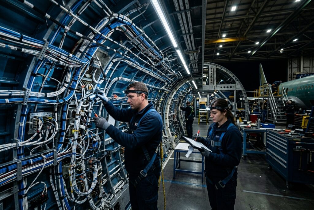
Launch vehicle wiring must survive extreme acceleration, vibration, and thermal loads during ascent, with zero tolerance for in-flight failure once the vehicle leaves the pad.

Design & Construction
Launch-Rated Vibration & Shock Design
Reinforced strain relief and vibration-damped routing withstand the extreme acceleration and shock loads experienced during launch and stage separation events.
Radiation and Thermal-Tolerant Materials
Radiation-tolerant insulation and thermal-tolerant jacketing maintain circuit integrity through the temperature extremes of ascent and orbital environments.
Manufacturing Process
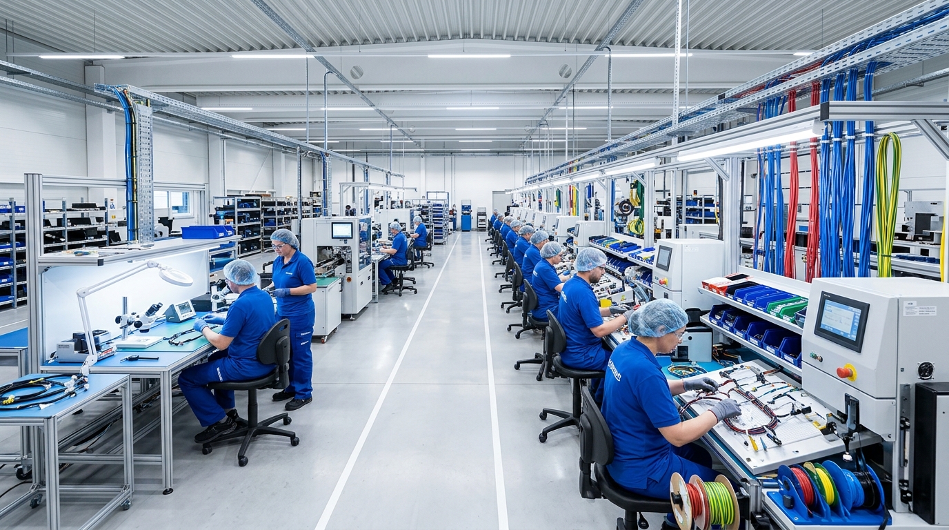
Built under AS9100D quality management with full first-article inspection and lot traceability, supporting launch vehicle integrators through rigorous qualification testing programs.
Typical Applications
- Stage separation signal wiring
- Avionics bay interconnects
- Payload fairing sensor cabling
- Propulsion system control wiring
- Telemetry and tracking harnesses
Common installations include Stage separation signal wiring, Avionics bay interconnects, and Payload fairing sensor cabling, where flight-critical reliability and stringent weight optimization are the primary design drivers. The same base design can also be adapted for Propulsion system control wiring and Telemetry and tracking harnesses with minor changes to connector type or cable length.
Technical Specifications
Standard configurations are available with the following technical specifications; custom configurations outside these ranges can be discussed with our engineering team. Wire Gauge: AWG 26 – 12. Conductor Count: 4 – 48 circuits. Insulation: Radiation-tolerant, high-temp fluoropolymer. Temp Range: -65°C to +260°C. Shock Rating: Launch and stage-separation qualified. Shielding: EMI-shielded telemetry circuits. Connector Standard: MIL-spec, launch-qualified.
Quality & Certification
Manufactured under AS9100D and ISO 9001 certification, with qualification testing documentation suitable for launch vehicle flight certification programs.
Customization & Lead Time
Standard lead time for the Space Launch Vehicle Cable Assemblies is 8–10 weeks prototype, 4–5 weeks production reorder. Connector type, cable length, and conductor configuration can be customized to match your exact application, including MIL-spec connector alternatives and shielding options for specific avionics or airframe integration requirements. Contact our engineering team with your drawings or requirements for a project-specific quote.
Why XinHarness
Launch vehicle cable assemblies run on the same AS9100D-certified lines as our satellite and avionics programs, extended to meet launch-specific qualification requirements. See the Aerospace industry page, or request a quote for your project. For related technical background, see our article on the impact of extreme temperatures on wire harness performance.
Frequently Asked Questions
All aerospace harnesses, including the Space Launch Vehicle Cable Assemblies, are manufactured under AS9100D quality management and can be built to MIL-DTL-27500 wire and connector specifications on request.
Every Space Launch Vehicle Cable Assemblies unit undergoes continuity, insulation resistance, and dielectric withstand testing, with additional environmental and vibration testing available for flight-critical applications.
Yes. Connector types, wire gauge, shielding, and routing length can all be customized to match your specific airframe and installation requirements — contact our engineering team with your drawings or specifications.