Overview
Body control and lighting circuits combine bus communication with switched power in a single sub-harness: headlamp and taillamp feeds, door module and switch panel wiring, and the CAN/LIN links that tie it back to the body control module.
Design & Construction
Bus & Switch Circuits
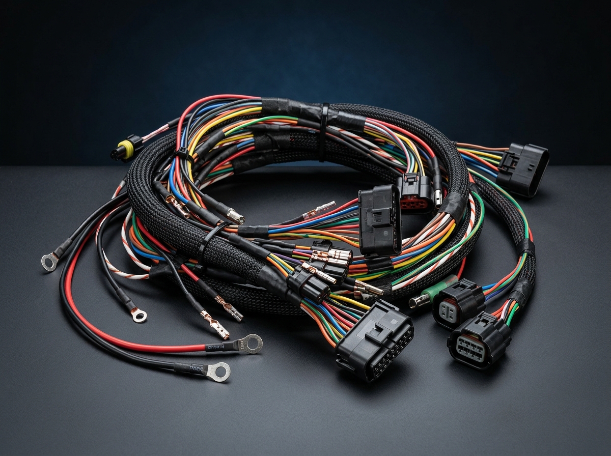
CAN, CAN FD, and LIN bus wiring is routed alongside switched power circuits for lighting and door modules, with connector pinouts matched to the customer’s BCM and module drawings.
Lamp & Connector Sealing
Exterior lamp connectors are sealed to IP67 with UV-stabilized jacketing for engine-bay and exterior routing, while interior lighting and switch circuits use standard automotive TXL insulation.
Manufacturing Process
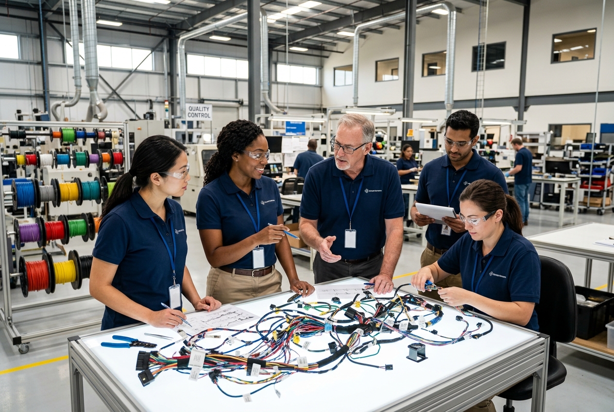
Assembled on IATF 16949-certified lines with the same crimp-force monitoring and PPAP documentation used across our automotive production, with 100% continuity testing before packing.
Typical Applications
- Headlamp and taillamp harnesses
- Interior lighting and switch panel wiring
- Door module interconnects
- Body control module (BCM) wiring
- CAN/LIN bus sub-harnesses
Common installations include Headlamp and taillamp harnesses, Interior lighting and switch panel wiring, and Door module interconnects, where vibration resistance and long-term durability under continuous thermal cycling are the primary design drivers. The same base design can also be adapted for Body control module (BCM) wiring and CAN/LIN bus sub-harnesses with minor changes to connector type or cable length.
Technical Specifications
Standard configurations are available with the following technical specifications; custom configurations outside these ranges can be discussed with our engineering team. Wire Gauge: AWG 20 – 14. Conductor Count: 2 – 48 circuits. Bus Support: CAN, CAN FD, LIN. Insulation: XLPE / TXL, 105–125°C rated. IP Rating: IP67 (exterior lamp connectors). UV Resistance: UV-stabilized jacket for exterior routing. Temp Range: -40°C to +125°C.
Quality & Certification
Manufactured under IATF 16949:2016 and ISO 9001:2015 certification with PPAP Level 3 documentation and AEC-Q200 qualified components where specified.
Customization & Lead Time
Standard lead time for the Automotive Body Control & Lighting Harness is 4–6 weeks prototype, 2–3 weeks production. Connector type, cable length, and conductor configuration can be customized to match your exact application, including alternative connector families, wire gauge, and shielding to match OEM or Tier 1 platform specifications. Contact our engineering team with your drawings or requirements for a project-specific quote.
Why XinHarness
Body and lighting sub-harnesses share tooling and process controls with our broader automotive harness capability. See the Automotive industry page, or request a quote for your project. For related technical background, see our article on our introductory guide to automotive wiring harnesses.
Frequently Asked Questions
The Automotive Body Control & Lighting Harness is manufactured under IATF 16949 process controls, with RoHS 3 and REACH-compliant materials as standard.
Lead times vary by volume and complexity; prototype and sample builds typically ship faster than production runs. Contact us with your specifications for a project-specific quote and schedule.
Yes, we support everything from low-volume prototype builds through high-volume production for automotive OEM and Tier 1 programs.