Overview
Battery-powered consumer devices need two related but distinct cable types: internal battery pack interconnects, and external charging cables that meet USB-C Power Delivery or equivalent fast-charge specifications. This line builds both.
Design & Construction
Battery Interconnect Wiring
Internal battery-to-PCB and cell-interconnect wiring is sized to the pack’s current draw, with connector and wire gauge selected to keep voltage drop within the battery management system’s tolerance.
Charging Connector Assemblies
External charging cables are built around USB-C PD, JST, or Molex connector families depending on the product’s charging interface, with cable construction rated for repeated plug/unplug cycles.
Manufacturing Process
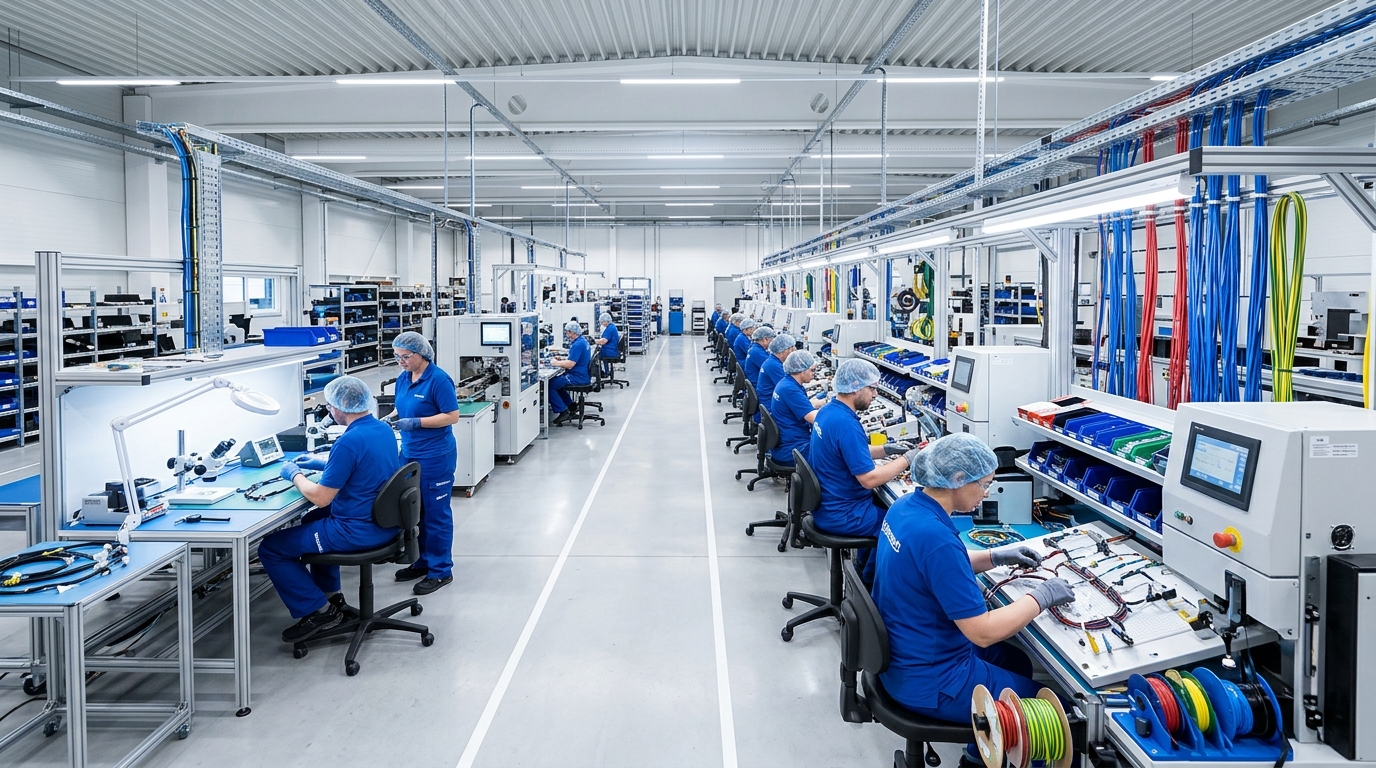
Production runs under our ISO 9001 quality system with RoHS 3 and REACH SVHC tested materials, scaling from prototype runs to dedicated high-volume lines as order size grows.

Typical Applications
- Power bank and battery pack interconnects
- USB-C PD charging cable assemblies
- Portable device battery wiring
- Small appliance battery pack cabling
- Charging dock and cradle cabling
Common installations include Power bank and battery pack interconnects, USB-C PD charging cable assemblies, and Portable device battery wiring, where signal integrity, EMI control, and compact flex-rated construction are the primary design drivers. The same base design can also be adapted for Small appliance battery pack cabling and Charging dock and cradle cabling with minor changes to connector type or cable length.
Technical Specifications
Standard configurations are available with the following technical specifications; custom configurations outside these ranges can be discussed with our engineering team. Wire Gauge: AWG 24 – 16. Conductor Count: 2 – 8 circuits. Voltage Rating: Up to 48V DC. Current Rating: Up to 10A. Compliance: RoHS 3, REACH SVHC tested. Connector Options: USB-C PD, JST, Molex. Temp Range: -20°C to +80°C.
Quality & Certification
Manufactured under ISO 9001:2015 certification, RoHS 3 and REACH (SVHC tested) compliant, with UL Recognized construction available for applicable cable and connector combinations.
Customization & Lead Time
Standard lead time for the Battery Pack & Charging Cable Assemblies is 3–4 weeks prototype, 10–15 days production reorder. Connector type, cable length, and conductor configuration can be customized to match your exact application, including connector type, cable length, and shielding configuration to match your device’s board layout and enclosure design. Contact our engineering team with your drawings or requirements for a project-specific quote.
Why XinHarness
Battery and charging cable work runs on the same fast-prototyping, volume-scalable lines as our broader consumer electronics cable production. See the Electronics industry page, or request a quote for your project. For related technical background, see our article on the benefits of twisted-pair wiring for reducing electromagnetic interference.
Frequently Asked Questions
Yes, shielded cable, braided or foil shielding, and ferrite options are available to control EMI/RFI in sensitive electronic applications.
We support a wide range of board-to-board, wire-to-board, and industry-standard connector families; provide your preferred connector part number or mating requirement and we will match it.
Yes, all our consumer and industrial electronics cable assemblies, including the Battery Pack & Charging Cable Assemblies, are manufactured using RoHS 3 and REACH-compliant materials.