Overview
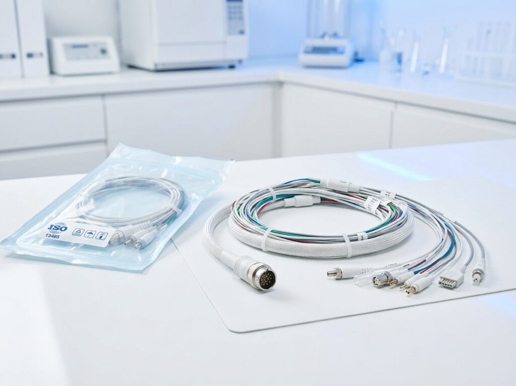
Imaging equipment runs high-density shielded signal cabling in electrically noisy environments, and in some cases needs non-ferromagnetic connector construction for use near the imaging field. This line covers ultrasound, CT, and general diagnostic imaging cabling.

Design & Construction
Shielded Signal Cabling
Foil-and-braid shielded pairs carry imaging signal data with low crosstalk, sized and configured to the equipment manufacturer’s connector and cable-count specification.
MRI-Compatible Construction
Where a design requires it, non-ferromagnetic connector and contact materials are available for cabling used near or inside an MRI suite, avoiding magnetic interference with the imaging field.
Manufacturing Process
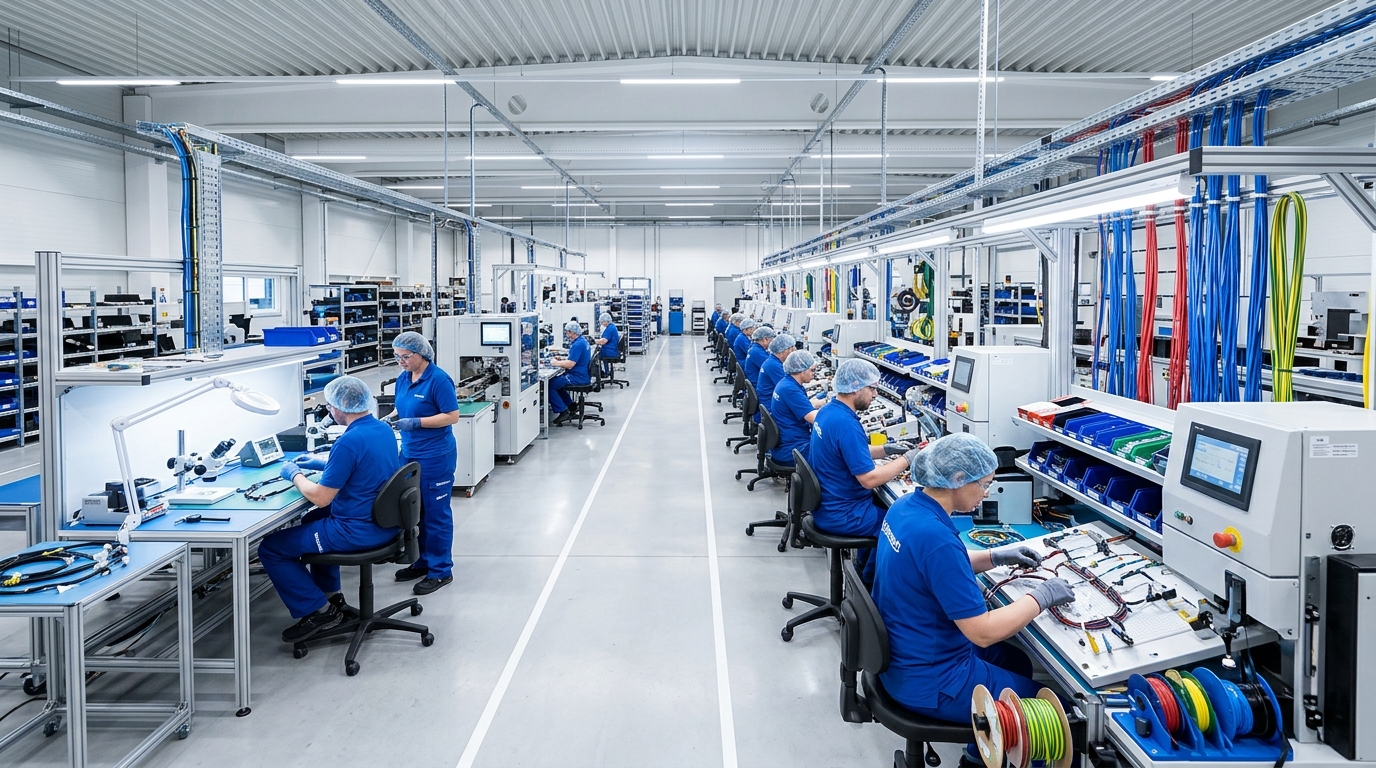
Assembled in our Medical Division cleanroom under ISO 13485 process controls, with lot-controlled shielded cable stock and finished-unit electrical testing before release.
Typical Applications
- Ultrasound probe cabling
- CT gantry interconnects
- MRI-compatible signal cabling
- Imaging console and workstation cabling
- Patient table interconnect wiring
Common installations include Ultrasound probe cabling, CT gantry interconnects, and MRI-compatible signal cabling, where biocompatibility, electrical safety, and continuous fail-safe operation are the primary design drivers. The same base design can also be adapted for Imaging console and workstation cabling and Patient table interconnect wiring with minor changes to connector type or cable length.
Technical Specifications
Standard configurations are available with the following technical specifications; custom configurations outside these ranges can be discussed with our engineering team. Wire Gauge: AWG 32 – 18. Conductor Count: 2 – 64 circuits, shielded pairs available. Shielding: Foil + braid for imaging-environment EMI. MRI Compatibility: Non-ferromagnetic connector options available. Temp Range: -20°C to +105°C. Cleanroom: ISO Class 100,000 (ISO 8). Biocompatibility: ISO 10993 data available on request.
Quality & Certification
Manufactured under ISO 13485:2016 and ISO 9001:2015 certification in a Class 100,000 (ISO 8) cleanroom, with ISO 10993 biocompatibility data available for patient-contact materials.
Customization & Lead Time
Standard lead time for the Diagnostic Imaging Equipment Cable Assemblies is 5–7 weeks prototype, 3 weeks production. Connector type, cable length, and conductor configuration can be customized to match your exact application, including connector type, cable length, and sterilization compatibility to match your device’s specific design requirements. Contact our engineering team with your drawings or requirements for a project-specific quote.
Why XinHarness
Imaging cable work is built in the same segregated Medical Division cleanroom as our diagnostic and monitoring equipment assemblies. See the Medical industry page, or request a quote for your project. For related technical background, see our article on the role of potting and conformal coating in wire harnesses.
Frequently Asked Questions
Medical assemblies including the Diagnostic Imaging Equipment Cable Assemblies are manufactured under ISO 13485 quality management for medical device manufacturing.
Yes, biocompatible and autoclave-sterilizable materials are available depending on the application and device contact requirements.
Yes, connector type, cable length, shielding, and sterilization compatibility can all be tailored to your specific medical device requirements — share your design specifications for a custom quote.